 Installation
Installation
By this time you should have a pretty good idea of how this system works and the function of the various components. So basically, all that is needed now is some installation tips and some additional explanation to tie all the components together.
The ECM is not designed to be mounted in an engine compartment
environment. So, one of the first decisions you’ll have to make
is where to mount the ECM in the passenger compartment. I fabricated
a bracket from angle  aluminum
and mounted mine under the passenger side vent door. The firewall,
just to the left of the vent door, provides a good location for
drilling the hole to pass the wire harness through. As you will see
by the size of the wire harness, the hole will have to be about an
inch in diameter. I used (and ruined!) a hole saw to make this hole.
If you had salvaged enough of the wiring harness with the ECM, it
will now reach the top of your inner right fender in the engine
compartment. Be sure to use a rubber grommet in the hole in the
firewall to protect the wires. And, don’t plug the wire harness
into the ECM while working with the cut wires. Remember that static
electricity!
aluminum
and mounted mine under the passenger side vent door. The firewall,
just to the left of the vent door, provides a good location for
drilling the hole to pass the wire harness through. As you will see
by the size of the wire harness, the hole will have to be about an
inch in diameter. I used (and ruined!) a hole saw to make this hole.
If you had salvaged enough of the wiring harness with the ECM, it
will now reach the top of your inner right fender in the engine
compartment. Be sure to use a rubber grommet in the hole in the
firewall to protect the wires. And, don’t plug the wire harness
into the ECM while working with the cut wires. Remember that static
electricity!
 I
found that the best way to splice and organize the wiring harness,
between the ECM and everything else, was to use double row terminal
strips. These are placed in a plastic crayon box (Wal-Mart, or steal
it from your kid!) and mounted under the hood on the inner fender.
This "junction box" provides a convenient location for tapping into
the circuits to monitor the electronics and for future
troubleshooting. The box also provides some protection from dirt for
the terminal strips. You will need four terminal strips to organize
all of the wires that go to the 24 pin A-B and 32 pin C-D connectors
located on the ECM, two strips with 12 positions each, and two strips
with 16 positions each. The terminal strips can be configured to the
same layout as the plugs at the ECM and makes it easy to keep track
of the different circuits. See the ECM
connector drawing and the wiring
diagram for the correct layout. This arrangement will give you
much better access to these circuits than Mr. Goodwrench ever dreamed
of! There are also two additional 3-position terminal strips that are
used. These are for the three weather tight fuse holders shown in the
wiring diagram.
I
found that the best way to splice and organize the wiring harness,
between the ECM and everything else, was to use double row terminal
strips. These are placed in a plastic crayon box (Wal-Mart, or steal
it from your kid!) and mounted under the hood on the inner fender.
This "junction box" provides a convenient location for tapping into
the circuits to monitor the electronics and for future
troubleshooting. The box also provides some protection from dirt for
the terminal strips. You will need four terminal strips to organize
all of the wires that go to the 24 pin A-B and 32 pin C-D connectors
located on the ECM, two strips with 12 positions each, and two strips
with 16 positions each. The terminal strips can be configured to the
same layout as the plugs at the ECM and makes it easy to keep track
of the different circuits. See the ECM
connector drawing and the wiring
diagram for the correct layout. This arrangement will give you
much better access to these circuits than Mr. Goodwrench ever dreamed
of! There are also two additional 3-position terminal strips that are
used. These are for the three weather tight fuse holders shown in the
wiring diagram.
The wiring diagram shows only the wiring associated with the fuel injection system. If you use an MSD ignition as I did, the wiring diagram for it is supplied with the unit or is available from MSD. A wiring diagram for the GM ignition module is enclosed separately in this article if you choose to go that route. The EFI setup is practically "stand alone", and with the exception of the 12 volt connections, ground, and the tach signal connection at the ignition, there are no other connections to your existing wiring.
The wiring diagram shows the terminal strips configured in the same way as the plugs on the ECM. To minimize clutter on the wiring diagram, the wiring between the terminal strips and the ECM is not shown. For example, the wire connecting A1 from the ECM plug to the terminal strip at location A1 is not shown. The wiring diagram does show which input or output signal is connected to A1 (in this case the fuel pump relay). You can also refer to the enclosed ECM connector drawing to determine the function of each wire and where it connects to the ECM plugs.
The color of the wires going to each sensor and the fuel pump relay are indicated on the wiring diagram to help identify the proper routing. With the exception of these, and the wires going to the ECM, you will choose all of the other wire colors, so label the diagram as you proceed. Except for the #12 wires, which are labeled in the wiring diagram, all wires are #14.
Use crimped wire terminals to attach the wiring to the terminal strips. Actually, I soldered all of these terminals as well, but that was very time consuming and probably not necessary. The ones that definitely should be soldered are the wires connecting the oxygen sensor, air fuel ratio meter and the ECM (D7). This is a low voltage signal and small differences are critical for accurate readings. I also connected all of the wires from the ECM to the terminal strips even though many will not be used. This just gave me a feeling of completeness while leaving no loose ends (literally!). I also wasn’t sure which ones I might want to use in the future. At this point you can complete all of your wiring per the enclosed wiring diagram, and at your own pace, as you continue to use your car. Just remember two things: leave the 30-amp fuse out of the fuse holder located near the starter relay, and leave the ECM disconnected from the wire harness. Take your time and keep everything well organized. This will really pay off if you have to do any troubleshooting later. Now would also be a good time to install the MSD ignition box or a suitable substitute.
The firing order for the 3.8L V6 is 1-6-5-4-3-2 and the SL6 is 1-5-3-6-2-4. The batch fire ECM fires injectors 1, 3 & 5 together and injectors 2, 4 & 6 together on the 3.8L. With the SL6, I wired it to fire 1, 2 & 3 and 4,5 & 6 respectively. This seems to work very well so I can only assume that I did the right thing. Use the OHM function on your DVM to determine which groups of three are together in the harness.
If you refer to my ECM connector drawing you will notice that many of the electronic circuits are listed as optional. Some of these are obvious but others may surprise you. For example, you don’t have to use the Idle Air Control motor, or for that matter even an oxygen sensor. I do strongly recommend that you use an oxygen sensor, if for no other reason than to monitor your fuel/air mixture. There are only three sensor inputs that absolutely must be used. These are the tach signal (B5), the throttle position sensor signal (C13), and the MAF sensor signal (B6). With only these inputs the engine would run quite rich because the ECM would always think the engine was cold, and it would always be in the open loop mode, but it would run. Without the Idle Air Control you would not have cold "fast idle" capability, and the ECM wouldn’t be able control the idle speed depending on conditions such as whether or not you are in gear or have the A/C on. The ECM also uses the Idle Air Control to maintain an idle speed high enough to ensure that the battery is not discharging, and to compensate for alternator load.
On the other end of the spectrum you can use many of the other circuits for their intended purpose, or to "fool" the ECM as can be done with the potentiometer in the temperature sensor circuit. The timing control circuit is one that has some potential, especially for a turbo application of this setup. You could use the GM ignition module with a Chrysler or Pertronix distributor pickup coil and have the ECM control your timing curve. Or, you could use the module only to trigger your ECM and leave the timing control disabled by not connecting module pins E, R and B to the ECM. (See the wiring diagram for the GM ignition module).
The important thing with whatever ignition is used is that it must generate a DC square wave tach signal. The AC sine wave signal from a magnetic pickup coil, such as used in the Chrysler ignition or a Pertronox conversion, will not properly trigger the ECM. The ECM is a digital device and can’t properly interpret an AC signal, so the AC sine wave must be converted to a DC square wave. If you use the GM ignition module to control your timing you would have to live with whatever timing the General had decided was best (no access to the ECM internal memory with a PC here). With the GM ignition module used to control your timing you would also have to disable the centrifugal advance in your distributor. For now, at least, I’d rather control my own timing curve.
If you use the GM ignition you wouldn’t need an MSD box to trigger the ECM but the MSD has other advantages. Remember, many MSD ignitions are also used on HEI GM cars. You should also consider that if you are still using points you could use the MSD ignition without converting to an electronic ignition. Once the MSD box is installed the points are only used as a low current switch and will last much longer than they would in a standard ignition. Even dwell angle is no longer a critical parameter.
For those of you interested in trying the GM ignition module I’ve included a separate wiring diagram for the module that shows how it would connect to the ECM. If you do decide to try this be sure that you use heat sink compound (auto parts store or Radio Shack) and provide a good metal heat sink for the module. I would think a good place to mount it would be in a metal box on your right inner fender.
You might also want to explore using the Electronic Spark Control (ESC) feature of the GM ignition. This is used along with a knock detector to prevent detonation. However, I’m not sure you could ever make full use of this function on the SL6 with mechanical lifters. I fear that the knock sensor would detect the tappet noise and drive the timing into full retard. Be sure those mechanical lifters are adjusted if you decide to try this!
I’m including all of this so you will be aware of the different possibilities and because I had researched this extensively when deciding how to build my own setup. I do think that the GM Ignition module is a potential low cost alternative. Someone who is interested in racing will have a different approach than someone with a daily driver with A/C and cruise control. The wiring diagram shows how I have built my setup (so far!).
There is one modification that you will need to make to the throttle body. This is to grind off the lower peg on the throttle plate actuator arm and substitute a 2 ¼" long #10-32 bolt in its place. This bolt will now reach out far enough to connect perfectly to a 2-BBL carburetor throttle cable and transmission kick-down linkage. Use four ny-lock nuts to position and separate the throttle cable and kick-down. If you’re converting from a 1-BBL carburetor you should get the throttle cable bracket and kick-down mechanism from a 2-BBL setup, just as if you were going to convert to a 2-BBL carburetor.
You will also need to fabricate an adapter to mount your throttle body to your manifold. For this I used a ¼" thick aluminum plate (www.thomasregister.com/olc/asapsource/home.htm) and cut a hole with a hole saw to match the throttle body bore. (As you can see my machinist skills are limited to the use of a hand drill). The throttle body was then attached to the aluminum plate from underneath using 5/16" flat head bolts, which now served as studs. This left a flat surface for mounting the plate to the manifold after the required mounting holes were drilled in the plate. You must also cut your manifold to remove any obstruction under the throttle body bore. And, of course you must make two gaskets to use between the adapter plate and the throttle body and the manifold.
While you’re making the adapter plate for the throttle body, also make one for your 2-BBL carburetor if you’re using a 4-BBL manifold. This will allow you to install your modified fuel injection manifold on the engine (with the injectors and fuel rail in place) and continue to use your carburetor while you finish the wiring and/or the fuel system plumbing. This works well when converting from a 2-BBL setup because the throttle cable and transmission kick-down linkage remain the same.
The GM throttle body has coolant line fittings that can be used to heat the throttle body. This prevents icing in the stock GM application. With the intake directly over the exhaust manifold on the SL6, I doubt this will ever be needed.
For my conversion I left my stock 5/16" fuel line in place (more on this later) and ran a new steel 3/8" feed line and new steel 5/16" return line. The fuel flow requirements of fuel injection are greater than for a carburetor, so a 3/8" feed line is required. The 3/8" feed line runs between the fuel rail and the electric fuel pump (I connected to the firewall end of the fuel rail) and high-pressure fuel filter that are mounted on the rear sub-frame. And, as was stated earlier, the return line runs between the fuel pressure regulator, which in my setup is mounted on the fuel rail, and the gas tank (or tank filler tube). Of course, flexible high-pressure line is used at each end of both of these metal lines.
The stock fuel line fitting at the gas tank (fuel tank sending unit) is a 5/16" nipple. I intend to eventually upgrade this to 3/8 " by either modifying my own sending unit or using one from a ’69 Barracuda/Dart 440 V8. Year One (www.yearone.com) sells this sending unit (P/N FA69) for $125. There was also an article in the August 1994 issue of Mopar Action, entitled "Fuel for Thought", that describes how to modify your own sending unit with 3/8" fuel line. In the mean time I’ve used a Spectra universal fuel filter (see new parts section) between the fuel tank and the fuel pump as an adapter. This is a low-pressure filter and comes with an assortment of hose barb fitting sizes that can be attached to the ends of the filter. So, it is perfect for adapting the 5/16" rubber fuel line from the tank to the 3/8" rubber fuel line that goes to the fuel pump, and can be changed to 3/8" at the input later. Furthermore, Accel recommends using a filter between the tank and the pump, so this worked out well.
A high-pressure fuel filter is used after the fuel pump. This filter provides the greater filtering capability (5 microns) needed with fuel injection and should still be used even though the Spectra filter is used before the pump. Connecting the flexible lines at the high-pressure side of the pump and in the engine compartment requires some careful attention. Any leak, especially in the engine compartment, could prove catastrophic. Based on the fact that many aftermarket fuel injection sources use hose barb fittings in similar applications, I felt somewhat comfortable using them here. I used AN–06 stainless steel braided AQP racing hose with the 3/8" fuel line, and 5/16" reinforced rubber fuel injection hose with the 5/16" line. To form the hose barb on the steel lines, use the first step of a double flair operation. If you don’t have a double flair kit, they are available from Harbor Freight Tools (www.harborfreight.com) P/N 40878-0VGA, $9. Don’t skip this step with the high-pressure lines!
If you’re using an accumulator in your fuel line, you’ll have to adapt the GM Saginaw fitting on the input side of the accumulator to your 3/8" steel line (Accel Jumper Line Kit 74731-A, and a 3/8" compression fitting from an auto parts store). Also, if you use an Accel adjustable fuel pressure regulator you’ll need a Saginaw to 5/16" adapter (Accel Jumper Line Kit 74731) for the return line. All of this plumbing work, with the exception of actually connecting the pump to the fuel tank, can be done while still using the car. To complete the plumbing you’ll need the modified manifold, fuel rail and injectors in place. Use Vaseline petroleum jelly on the injector o-rings to ease installation and later removal. Do not use silicone grease! Silicone products, unless they are labeled "sensor safe", will destroy your oxygen sensor.
The next major task is to decide how you want to configure the air intake ductwork. I had previously cut a hole in my left inner fender to use as a cold air intake for my Super Six set up. Not wanting to leave this gaping hole unused, I decided to use the same route for my new ductwork. This pretty much forced me to place the air box (filter housing) outside of the engine compartment in the top of the wheel well. As it turned out this worked very well, but did required a lot of fabricating and parts from two different GM air boxes. One half was from a ’91 Ciera 3.3L, and the other half was from a ’87 LeSabre 3.8L. I think the simplest solution for most would be to attach a K&E cone filter directly on to the MAF sensor so that the filter would be located right behind the battery. This filter would need some support. As I said earlier there will probably be as many different ways of fabricating this ductwork as there will be EFI conversions. Again, it is important that all the ductwork be air tight, but especially between the MAF sensor and the throttle body.
OK, I’ll have to admit, I was a little bit chicken at this point! I didn’t know of anyone who had ever done this conversion, and everyone I mentioned it to was extremely skeptical. In fact, the more people seemed to know about cars, the more skeptical they were! So, although I was confident (??), I decided to hedge my bets anyway. If you recall I had left my stock 5/16" fuel line in place when I installed my new fuel lines. I now used this line to feed a low pressure electronic fuel pump in the engine compartment. With this I could run a carburetor right up until the time I switched over to EFI. And, now that I have EFI, I can substitute the carburetor for my throttle body in about 10 minutes if for any reason the EFI system fails. I realize most will not want to bother doing this, but I liked knowing I had the option. An added benefit to this arrangement is that I now have a very convenient way of getting gas for my outboard motor and lawn mower! To select the proper fuel line I used an electronic fuel tank selector valve (www.jcwhitney.com, P/N 81ZX2686W) at the gas tank. This valve is connected in reverse, so that instead of selecting one of two tanks it now selects one of the fuel lines. One switch controls both the selector valve and the low pressure fuel pump. This means that whenever the pump is on, the fuel is also diverted to it.
So now you have all the wiring done, all the plumbing connected and the throttle body on your fuel injection manifold. Just plug the wiring harness into your ECM, install the 30-amp fuse and you’re ready to go. But wait! Before you start the engine, turn on the fuel injection system switch and thoroughly check for leaks. The fuel pump will only run for about 2 seconds so you will have to turn the switch on and off a few times to build up the pressure in the fuel rail. This is part of the safety function of the ECM that prevents the fuel pump from running without the tach signal. Before starting the engine for the first time you should also set the Throttle Position Sensor to the recommended settings. With your fuel injection switch turned on, connect the positive lead of your DVM to C13 (throttle position sensor signal), and the negative lead to ground, while on the 2-volt DC scale. Then loosen the TPS hold-down screws and adjust the TPS position to get a reading of 0.40 +/- .05 volts on the DVM. Next, tighten the screws and check that as the throttle is opened, the voltage steadily increase to about 4 volts. An analog voltmeter is actually best for the second part of this test.
No leaks? TPS adjusted? Then turn the 20K potentiometer to maximum resistance (if you're not using a temperature sensor) and start it up! When the engine starts turn the pot down to a lower value. I think you’re going to be very pleased with the way this setup runs. The only "bug" that I have to work out is the idle speed, which is now running at about 800 rpm. I could solve this problem by disconnecting the IAC motor, but as I said before I’d like to use the IAC motor if at all possible. A couple of things that helped lower the idle some on my setup were to apply 12 volts to ECM terminal D11 (power steering switch signal), and to connect B10 to ground (park/neutral switch signal).
Now that the engine is running you can use your fuel/air meter, adjustable fuel pressure regulator, dwell meter, tachometer and the ECM itself to do some fine-tuning. I’ve only had limited experience here but I’ll tell you what I’ve learned so far.
The first step in the tuning process is to disconnected (and plug) the vacuum line from the fuel pressure regulator, and, with the engine running, adjust the fuel pressure for 40 PSI. Then reattach the vacuum line. Next, adjust your Idle Air Control (IAC) using the following procedure:
Now you can start the engine again and enter the ECM field service mode. This mode is entered whenever the Diagnostic/Field Service Switch is turned on with the engine running. When in this mode, the Fault Code Light will indicate whether or not the ECM is operating closed loop. During closed loop operation the ECM is continuously adjusting the fuel/air ratio to maintain a 14:1 ratio, and the light will blink at a rate of one blink per second. The light will stay on longer when the mixture is rich and off longer when the mixture is lean, and during closed loop will hunt back and forth between these two conditions. In open loop the light flashes at a rate of two and one half times per second. Generally, you’ll only be in closed loop operation during idle and at cruise, and only when the engine is warmed up. My setup goes in and out of closed loop at idle and I’m assuming that this is normal (?). If you don’t enter closed loop, the first suspect would be the oxygen sensor. By the way, this is a good time to mention that you should never connect an ohmmeter across an oxygen sensor. The voltage from the battery in the meter is enough to blow the oxygen sensor.
 You
may have heard that these computer-controlled systems take a while to
learn how to best control the engine. This is true. The reason for
this is that the computer has been programmed to "believe" the input
it receives from the oxygen sensor above everything else. Since the
oxygen sensor measures the final results of the combustion process
the computer uses this input to interpret the readings that it
receives from the other sensors. This allows the computer to
compensate for things like the aging of sensors, small vacuum leaks
and other developing engine inefficiencies. It then stores this
information in its Random Access Memory (RAM). However, RAM is lost
whenever power is disconnected from the ECM, and as a result the
learning process has to be repeated when the power is restored. Often
the engine will not initially run as well as it had prior to the loss
of power to the ECM. (Actually, it will run using default settings
just as if it didn’t have an oxygen sensor.) Then as the oxygen
sensor again "teaches" the ECM how to interpret the readings it
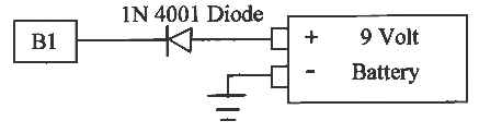
receives from the other sensors, things will return to normal. To
avoid this loss of memory you can place a standard 9 volt battery
with a 1N4001 diode across ECM terminal B1 (12 volt input) and ground
whenever you disconnect the battery. This is optional and will allow
the ECM to retain its memory when the 12-volt battery is removed. It
is important that a diode be placed in this circuit as shown here.
The diode prevents a "melt down" of the 9 volt battery when the 12
volt battery is also in place. The diode is available from Allied
Electronics (www.alliedelec.com),
Allied stock # 568-0141, $0.03 ea. or at Radio Shack stores as P/N
276-1101 (2 for $0.49). Radio Shack stores also carry the 9V Battery
Snap Connectors as P/N 250-324 (5 for $2). I used alligator clips on
this so that it can be put in place whenever desired. I don’t
recommend leaving it in the ECM circuit.
You
may have heard that these computer-controlled systems take a while to
learn how to best control the engine. This is true. The reason for
this is that the computer has been programmed to "believe" the input
it receives from the oxygen sensor above everything else. Since the
oxygen sensor measures the final results of the combustion process
the computer uses this input to interpret the readings that it
receives from the other sensors. This allows the computer to
compensate for things like the aging of sensors, small vacuum leaks
and other developing engine inefficiencies. It then stores this
information in its Random Access Memory (RAM). However, RAM is lost
whenever power is disconnected from the ECM, and as a result the
learning process has to be repeated when the power is restored. Often
the engine will not initially run as well as it had prior to the loss
of power to the ECM. (Actually, it will run using default settings
just as if it didn’t have an oxygen sensor.) Then as the oxygen
sensor again "teaches" the ECM how to interpret the readings it
receives from the other sensors, things will return to normal. To
avoid this loss of memory you can place a standard 9 volt battery
with a 1N4001 diode across ECM terminal B1 (12 volt input) and ground
whenever you disconnect the battery. This is optional and will allow
the ECM to retain its memory when the 12-volt battery is removed. It
is important that a diode be placed in this circuit as shown here.
The diode prevents a "melt down" of the 9 volt battery when the 12
volt battery is also in place. The diode is available from Allied
Electronics (www.alliedelec.com),
Allied stock # 568-0141, $0.03 ea. or at Radio Shack stores as P/N
276-1101 (2 for $0.49). Radio Shack stores also carry the 9V Battery
Snap Connectors as P/N 250-324 (5 for $2). I used alligator clips on
this so that it can be put in place whenever desired. I don’t
recommend leaving it in the ECM circuit.
In his book How To Repair & Modify Chevrolet Fuel Injection, Ben Watson tells us that we can use a dwell meter to measure duty cycle, and a tachometer to measure frequency. To convert dwell to duty cycle you multiply the dwell read on the 4-cylinder scale by 1.1. To convert RPM to frequency in Hz. you divide the RPM read on the 4-cylinder scale by 30. I wanted to prove this for myself so I developed a reasonable explanation and "proof". These two concepts can be confusing and I didn’t want to burden every reader with the explanations. So, I’ve enclosed them as an appendix to this article. Check it out if you need to be convinced. However, you don’t need to know all of this to make the measurements.
To measure the injector duty cycle, attach the positive lead of a dwell meter to ECM connector location D14, D15, D16, or C15 and the negative lead to ground. Then, when you are on the 4-cylinder scale, the duty cycle is equal to 1.1 times the meter reading. For all practical purposes the duty cycle can be considered the same as the meter reading. Now you can check to insure that the injector duty cycle increases rapidly as the throttle is quickly opened. It is this action by the ECM that takes the place of your accelerator pump. Also, check to insure that the duty cycle increases as engine speed increases. While it is duty cycle that is measured with the meter, it is actually the pulse width that determines how long the injectors are open and is actually what controls the mixture. To determine the actual pulse width you must also measure the frequency of the injector firings and divide that into the duty cycle. The relationship between duty cycle and pulse width is also given in the appendix to this article, along with the reason that the dwell meter and tachometer can be used to make these measurements.
This might also be a good time to verify that your MAF sensor is operating correctly. The Delco MAF sensor used with the 3.8L engine uses the preferred (my opinion) heated mylar film as opposed to the more common "hot wire" technique used in the Bosch MAF sensors. (The Bosch MAF is used in many GM V8 engines). The Delco MAF sensor produces a square wave pulse to control a heating element imbedded in a mylar film that is housed in the sensor. The frequency of the pulse is varied to maintain a constant temperature on the mylar film. The volume, temperature, and humidity of the air entering the engine all have the cumulative effect of cooling the mylar film. These parameters also determine the density of the air being ingested by the engine. So, by measuring the frequency of the electrical pulses needed to maintain a constant temperature, the ECM can determine the density of the air entering the engine and adjust fuel delivery accordingly.
The MAF sensors that I’ve measured generated a frequency of 8 to 12 Hz with the fuel injection switch on and the engine off, and about 40 Hz with the engine running at 800 RPM. To check that your MAF is operating properly attach the positive lead of your tachometer to ECM terminal B6 (MAF sensor signal) and the negative lead to ground. Then, as stated earlier, take a reading on the 4-cylinder scale and divide by 30. The readings should agree with those listed above and steadily increase as engine speed increases. Any rapid increase or decrease in frequency here would indicate a problem.
With the engine off, the diagnostic/field service mode switch can be used to read trouble codes stored by the ECM. When this switch is turned on, along with the fuel injection switch, a code of 12 (blink…..blink, blink) will be flashed three consecutive times on the fault code light to indicate that the ECM is operating properly. That code will be followed by codes for whatever faults the ECM has detected since it was last cleared. If there are no fault codes then code 12 will continue to be flashed as long as the switches are left on. Each fault code stored in memory will be flashed three consecutive times. When all of the fault codes stored in memory have been flashed, code 12 will again be flashed three consecutive times. For example, fault codes 42 and 43 will always be present if you’re not using a GM ignition, and in this case simply indicates that the ECM did not detect the expected signals. To remove trouble codes from the computer memory turn the fuel injection switch off and remove the fuel injection 30 amp fuse for 10 seconds (be sure your 9 volt memory saver is not in place). NOTE: To prevent damage to the ECM, always turn the fuel injection switch off before connecting or disconnecting power to the ECM.
Finally, you’ll need an applicable GM or aftermarket service manual (Haynes or Chilton’s) to interpret all of the trouble codes. If you want to explore all of the wiring in detail there is no substitute for the GM service manual. Also, I highly recommend How To Repair & Modify Chevrolet Fuel Injection by Ben Watson for a good understanding of how the GM system works.
Well there you have it. I hope I haven’t made too many errors. If you find any let me know on the Slant Six Forum and I’ll correct them. I’m sure this is more than you ever-ever wanted to know about GM cars, and I’m also sure that it’s more than most GM car owners know about their own cars. Just don’t let them know what you have under that hood! Well… at least it’s still good old American technology.