Early A-body Instrument Regulators
by Chuck Rivers
If you have owned an early A-body car long enough you probably
have experienced the failure of the gas and temp gauges. The cause of
the failure of both gauges is the instrument cluster regulator. This
regulator maintains a constant voltage to the gas and temp gauges so
that they won't fluctuate when the battery voltage changes during
charge and discharge cycles.
In these early cars, the regulator was built into the gas gauge,
which made repair difficult. The regulator is actually a bimetal
spring with a coil wound around it. As the current going through the
coil heats up the spring, it breaks a set of points that disconnects
the voltage from the gauges. The output of the regulator is actually
a pulse of about 4 volts (2 per second). In 1967, Chrysler made the
instrument regulator a unit that plugs into the back of the
instrument panel. This article shows how to use the 1967 regulator to
repair your gauges.
NOTE: If your gauges work but read low, this repair will probably
not restore full functionality to the gauges. This is because some of
the current from the replacement regulator will feed back into the
old internal regulator. On one car I tried with partially functioning
gauges, it brought the readings up closer to normal, but not all the
way. If your gauges are completely dead, this should restore full
functionality.
 My
test setup was the instrument panel from a 1963 Dart. You should be
able to duplicate this setup on a '63-'66 Dart, Valiant or 'Cuda. It
may also work on the '60-62 Valiant and Lancer, but I do not have any
other instrument panels to play with. You will need to find the
appropriate places to connect the new regulator. You can also do this
while the panel is installed in the car if you can get your hands
back there to attach the wires. (Disconnect the battery first!)

 You
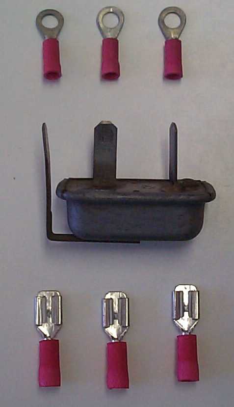
will need 3 "spade" connectors, 3 "ring lugs" (#8), 3 pieces of wire
about 6" long and the new regulator. Use a crimping tool to assemble
the connecting wires. The killer here is the regulator. At one store
I paid $27!
The bottom of the regulator has one terminal marked "I". This
connects to the ignition circuit. The terminal spot-welded to the
cover is the ground, and the remaining terminal is the regulator
output.
Shown below is the unit attached to the instrument
panel.
It would also be a good idea to tape up the regulator to prevent
shorting to other terminals on the panel.

Wire placement
 My
test setup was the instrument panel from a 1963 Dart. You should be
able to duplicate this setup on a '63-'66 Dart, Valiant or 'Cuda. It
may also work on the '60-62 Valiant and Lancer, but I do not have any
other instrument panels to play with. You will need to find the
appropriate places to connect the new regulator. You can also do this
while the panel is installed in the car if you can get your hands
back there to attach the wires. (Disconnect the battery first!)
 You
will need 3 "spade" connectors, 3 "ring lugs" (#8), 3 pieces of wire
about 6" long and the new regulator. Use a crimping tool to assemble
the connecting wires. The killer here is the regulator. At one store
I paid $27!