Slant Six Forum
https://www.slantsix.org/forum/

dual ballast resistor loop
https://www.slantsix.org/forum/viewtopic.php?t=37996
Page 1 of 1

Author:  oklahoma joe [ Wed Nov 18, 2009 4:15 am ]
Post subject:  dual ballast resistor loop

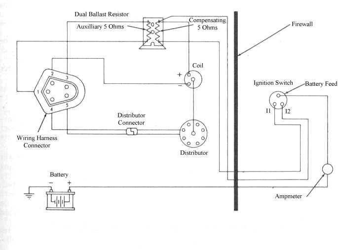
I have a 64 barracuda that has been converted at some time in the past to a 73 engine and electronic ignition. I am trying to sort out the ignition wiring and have a question about the dual ballast resistor. The diagrams I see for it have what looks to be a loop between the blue wire terminals that connecting two resistors(bottom of the resistor in the digram. Mine did not have that on it so I made one for it. What does it do? does it need to be there? or am I reading the diagrams wrong?
http://www.slantsix.org/articles/elect_ ... gn_wir.jpg

thanks joe

:)

Author:  SlantSixDan [ Wed Nov 18, 2009 6:15 am ]
Post subject: 

Yup, it's supposed to be there if you are using a dual ballast resistor and 5-pin module.

Author:  Joshie225 [ Wed Nov 18, 2009 7:05 am ]
Post subject: 

The loop is to supply the switched 12V to the other side of the ballast resistor. I suspect you have a 4-pin module if the car ran without 12V being applied to one end of both resistors.

Author:  oklahoma joe [ Wed Nov 18, 2009 2:57 pm ]
Post subject: 

Its a five pin cpu it would run before but not turn off. had to pull the coil wire to get it to stop. Hope fully the rewire will fix it. It looks pretty ugly right now but its just temporary, unless it works.


thanks

Joe

Author:  bigslant6fan [ Sat Nov 21, 2009 8:27 pm ]
Post subject: 

The IGN switch kills all power to the resistor and IGN box.If it runs with the IGN switch off,a battery or alternator output wire could be melted or shorted to the IGN run wire,or the IGN switch could be bad.Using graphite based lock lubricant on the IGN switch could cause this

Page 1 of 1 All times are UTC-08:00
Powered by phpBB® Forum Software © phpBB Limited
https://www.phpbb.com/